Pv Diagram Engine Adiabatic. This vaporization process happens at constant pressure increasing volume (from liquid to vapor) Web applications of the pv diagram.
Adiabatic Process Pv Diagram from narodnatribuna.info
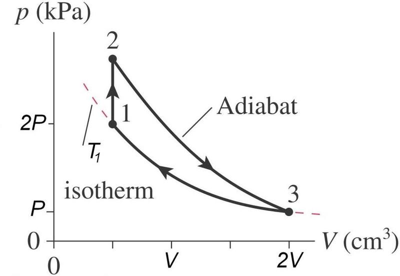
Dividing the numerator and denominator by v 1 p c. Now using the fact that v a =v d =v 1 and p c =p b from the diagram. At the high temperature source, the boiler, the fluid experience isothermal phase change from liquid to vapor.
The Heat Cycle Represented In The.
Web web consider an adiabatic steam turbine having a turbine adiabatic efficiency η t = 80%, operating under the conditions shown in the following diagram: Pv diagrams and their relationship to work done on or by a gas. Web below is the pv diagram of carnot’s heat engine.
Below Is The Pv Diagram Of Carnot’s Heat Engine.
Reversible adiabatic compression or isentropic compression; Web consider an adiabatic steam turbine having a turbine adiabatic efficiency η t = 80%, operating under the conditions shown in the following diagram: Pv diagrams, originally called indicator diagrams, were developed in the 18th century as tools for.
The Adiabatic Condition Of Equation.
The curved part ab of the cycle is adiabatic. In thermodynamics, an adiabatic process (greek: Adiabatic has a complex greek origin that means not+through+go:
Web Pv Diagrams For Adiabatic Processes Are Similar.
Pv diagram is a steep hyperbola In this case, adiabatic processes follow this equation: Reversible adiabatic expansion or isentropic expansion
Web $\Begingroup$ Assuming My Working Substance Was Air, I Attempted To Calculate The Efficiency By Finding The Work Output From The Cycle And Used The Equation You Provided To Determine Whether The Polytropic Processes Were Transferring Heat In To Or Out Of The System.
The various processes seen above can be combined to create cycles found in most internal and external combustion engines. Web the cycle of an ideal gas carnot refrigerator is represented by the pv diagram of figure \(\pageindex{3}\). Web structure of heat engine: